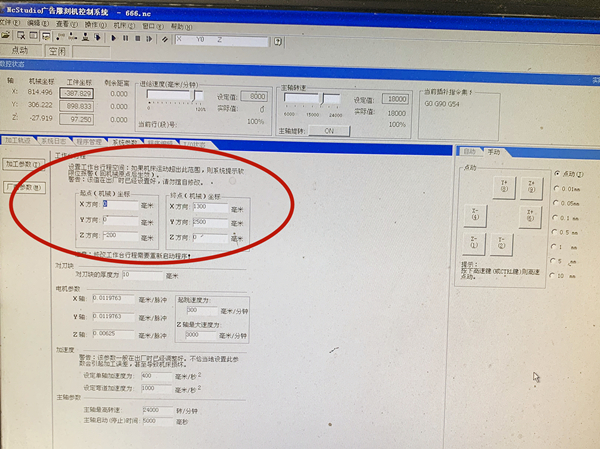
In a general sense these location of x,y,z axis form a set of co-ordinates that tell the CNC control where the spindle and tool tip should move. It is very common, but not absolutely necessary, to find these match the intuitive understanding of drawing space, that is, the X direction is left-right, the Y direction is front to back (rather like a graph) and the Z direction is up-down.

You can also re-assign these directions to suit the job. The + and – directions can also be assigned to suit.
You will often find that X0 Y0 Z0 is at a corner or datum hole on the part being machined, but it can be anywhere.
It is very common to program in a way which assumes the centreline of the spindle is what is being referenced in the program, at the very tip of the tool, but again this isn’t universal. The tool can also be programmed to reference the outside surface, or diameter.
So a co-ordinate of X-200 Y300 Z-10 will direct the tool to a position -200 mm (or inches) from X0, 300 mm from Y0, and -10 mm (usually downwards) from Z0.
The above description is for reference only. If you have any problems with CAMEL CNC machines, please feel free to contact the after-sales service department.
Post time:October-21-2020
